Introduction
The term 'electricity' is referred to any effect resulting from the existence of electric charge which may be either stationary or moving hence, the branch of physics that deals with an electric charge either at rest or in motion is called electricity. According to the state of the electric charge, electricity may be divided into two branches which are electrostatics and current electricity.
- The branch of physics which deals with electric charge at rest is called static electricity or electrostatics.
- The branch of physics which deals with charges in motion is called current electricity.
Electric current
The electric current is similar to water current, air current, etc.
The water current is due to flow of water, air current is due to flow of air and the electric current is due to flow of electric charge. Thus, the flow of electric charges produces electric current. Whose magnitude is measured by the flow of charges in one second.
Thus, the rate of flow of charges is called electric current. It is denoted by 'I' or 'i'. If 'q' is the magnitude of charges flowing in time 't' (sec), then electric current 'I' is expressed by,
Electric current (I) = \( \frac{\text{Amount of charges flow}}{\text{Time taken}(t)} \)
\( \therefore I=\frac{q}{t} \) ①
Since, charge is quantified i.e. q=ne, Where n' is the number of charge carriers, each having charge \( e \), we can write,
\( I = \frac{ne}{t} \)
If small amount of charge \( dq \) flows in small time dt: so,
current \( I = \frac{dq}{dt} \) ②
→ In SI system the unit of current is coulomb/second or ampere and its symbol is 'A'.
i.e. \( 1\,A = \frac{1\,C}{1\,s} \)
A current flowing through a conductor is said to be one ampere; if a coulomb of charge flows through the conductor in one second. Smaller units of the current are milliampere(mA) microampere(μA) and picoampere (pA). Electric current is a scalar quantity and is measured using an instrument called Ammeter.
Toward the beginning of the 19th century, the chemical cell was discovered. At that time, the direction of current along the conductor was unknown. So, it was assumed that the flow of current is the flow of +ve charge from +ve terminal or pole of a cell to the −ve terminal of it. But after the discovery of electron by J. J. Thomson, it was proved that the flow of current is the flow of −ve charge from −ve terminal of the battery to the positive (+ve) terminal of it.
Types of Electric current
→ Electric current are of 2 types:
i) Direct current (DC)
→ Direct current is that current whose magnitude as well as direction remains constant at all times. For examples, the current flowing through a resistor connected to a battery is a direct current (D.C).
Alternating current (AC)
Alternating current is that current whose magnitude and direction changes continuously periodically. For eg.: An a.c generator produces an a.c. current.
Drift velocity (Vd) / Mechanism of metallic conductor
There are few electrons which are not attached to the orbits of atom. Also some electrons are loosely bound in atomic orbits of metals. They are in a random motion like the molecules of a gas confined in a container. These electrons are called free electrons.
These free electrons move randomly in all direction. So, there is no net flow of charge in any direction.
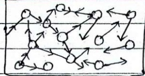
In the absence of external electric field in the conductor, the free electrons are in thermal equilibrium with the rest are in random motion. So, the average velocity of the electrons in a direction is zero and as a result, this motion does not make up a net transport of charge across any section of the conductor. Hence, there is no current in the conductor.
When the electric field is applied on the conductor, each electron is acted by an electrostatic force, and the electrons get accelerated in a direction opposite to that of the field. Hence these electron gains velocity and kinetic energy. These electrons however collide with atom or ion on lattice site of the metal. During collision, the electrons give up their energy to the atoms and their velocity decreases. However the electron again accelerates and makes collision with atoms. Due to the repeated collision, the average acceleration of electrons is reduced to zero and the electrons thus acquire a constant average velocity opposite to the direction of the electric field. This velocity is called drift velocity which is responsible for the flow of a current through the conductor. Thus, the average velocity attained by an electron when a potential difference is applied is called the drift velocity. It is very small of the order of \( 10^{-4} m/s \) and depends on the P.d. applied across the conductor, while the thermal speed of random motion is of the order of \( 10^{5} m/s \) and depends on the temperature.
Expression for Drift velocity \( V_{d} \)
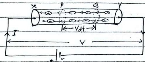
Fig: Flow of electrons
Consider a uniform metallic wire (conductor) XY of length l' and cross section area A'. A potential difference V is applied across the ends X and Y of the wire. This causes an electric field at each point of the wire of strength.
\( E=\frac{V}{l} \) ①
Due to this electric field, the electrons gain a drift velocity Vd opposite to direction of electric field. If q' be the charge passing through the cross-section of the wire in t' seconds, then, current in the wire is given by:
\( I = \frac{q}{t} \)
The distance travelled by each electron in time \( t' = V_{d} \times t \) — ②
Let us consider two planes P' and S' at a distance \( V_{d}t \), in the conductor. Then, the total charge flowing in time \( t' \) will be equal to the total charge on the electrons present within the cylinder. The volume of this cylinder = \( AV_{d}t \) — ③
If n' is the number of free electrons in the wire per unit volume then, number of free electrons in the cylinder = \( nAV_{d}t \)
Total charge flowing through the cross-section of the wire
(q) = number of free electrons × electron charge
i.e. \( q = nAV_{d} \cdot e \)
or, \( \frac{q}{t}=nAV_{d}e \)
or, \( I = nAeV_{d} \) → ⑤ \( \left[\therefore I = \frac{q}{t}\right] \) (trick: I = neAVd)
or, \( \frac{I}{A} = neV_{d} \)
\( \therefore J = ne V_{d} \) → ⑦
\( J=\frac{I}{A}= \) current density.
from ⑤, electric current in a conductor is directly proportional to drift velocity, i.e. \( I \propto Vd \).
Ohm's law
The relation between electric current and P.d was discovered by German Scientist George Simon Ohm in 1827. On the basis of experimental observation, he kept this relation in the form of a law which is called Ohm's law in honour of his name.
→ The ohm's law states that, "Under constant physical condition, i.e. temperature and dimension of the conductor, the current flowing through it is directly proportional to the potential difference applied across it."
If I be the current flowing through the conductor, V be potential difference across the ends of conductor then, Ohm's law is mathematically defined as:
\( I \propto V \)
or, I = constant × V
or, \( V = IR \)
Where, \( C = \text{conductance} = \frac{1}{R} \)
Where, R → is also a constant called resistance.
This eqn is similar to the equation of a straight line passing through the origin, y=mx. Hence, the slope of V-I graph gives the resistance of a material i.e. slope \( = \frac{V}{I} = R \).
Experimental verification of Ohm's law
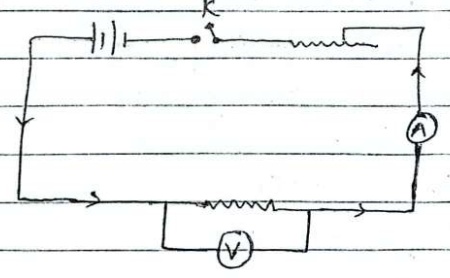
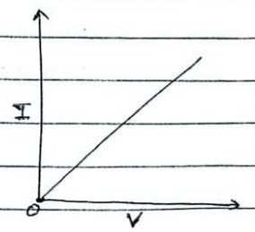
→ Ohm's law can be verified by using a circuit as shown in figure above.
Resistor R' is connected in series with a battery, an ammeter and rheostat through one way key k in the circuit. A voltmeter V is connected across R' to measure the potential difference across it.
An ammeter measures the current flowing through R'. By adjusting rheostat and closing key 'k', the ammeter and voltmeter reading are noted. By adjusting rheostat different positions, the different sets of voltmeter and ammeter readings are taken. When a graph is plotted between I and V, a straight line is obtained which passes through the origin as shown in figure: This shows that \( I \propto V \), which is Ohm's law. Hence it is verified.
Electrical resistance
→ An opposition offered by the conductor to the flow of charge is known as its resistance R'. Mathematically, it is defined as the ratio of P.d applied and current flowing through the conductor.
i.e. \( R = \frac{V}{I} \) \( [\because V = I R] \)
The symbol of resistor is —□— or —R—. In SI system, the unit of resistance is volt/ampere or ohm (Ω).
→ from many observations, it has been found that at constant temp, the resistance R of a conductor is directly proportional to its length l and inversely proportional to the cross-sectional area A'.
→ let L' and A' are length and cross-sectional area of a conductor respectively then,
\( R\propto l \) — ①
\( R\propto\frac{1}{A} \) — ②
Combining eq.① and ②.
\( R\propto\frac{\ell}{A} \)
or, \( R = \rho \frac{\ell}{A} \) —③
Where, ρ is a proportionality constant known as resistivity or specific resistance of a conductor.
Resistivity / specific resistance
→ We know that.
\( R = \rho \frac{\ell}{A} \)
\( \Rightarrow \rho = \frac{RA}{\ell} \) —③
If \( A = 1m^{2} \) and \( \ell = 1m \), then, from ③, we get.
\( \rho = R \) —④
Thus, the resistivity or specific resistance of material of a conductor is defined as the resistance of the conductor of unit cross-sectional area per unit length. Its SI unit is \( \Omega m \).
Conductance 'C'
→ It is defined as the reciprocal of resistance of a conductor. It is denoted by 'C'. So,
\( C = \frac{1}{R} \)
Unit of conductance \( C = (ohm)^{-1} \) or mho or siemen in SI system.
Conductivity or specific conductance (\( \sigma \))
→ The reciprocal of resistivity of a conductor is called conductivity. It is denoted by \( \sigma \). Thus \( \sigma = \frac{1}{\rho} \). In SI system, unit of conductivity is \( \Omega^{-1} m^{-1} \).
Effect of Temperature on Resistance of a conductor
→ It has been observed that the resistance of a conductor increases with the increase of temperature of the conductor.
→ If a conductor has resistance \( R_{0} \) at \( 0^{\circ}C \) and \( R_{t} \) at \( t^{\circ}C \),
then, increase in resistance \( (R_{t}-R_{0}) \) is directly proportional to initial resistance \( R_{0} \) and rise in temperature \( (\theta_{t}-\theta_{0}) \). So
$$ (R_{t}-R_{0}) \propto R_{0}(\theta_{t}-\theta_{0}) $$
$$ (R_{t}-R_{0})=\alpha R_{0}(\theta_{t}-\theta_{0}) $$
$$ R_{t}-R_{0}=\alpha R_{0}\Delta\theta $$
$$ R_{t}=R_{0}+\alpha R_{0}\Delta\theta $$
$$ \therefore\quad R_{t}=R_{0}(1+\alpha\Delta\theta) \quad \text{(1)} $$
Here α is a proportionality constant known as temperature coefficient of resistance of a conductor.
→ From above eqn, we have,
\( \therefore \alpha = \frac{R_{t} - R_{0}}{R_{0} \Delta \theta} \)
→ Hence, temperature coefficient of resistance of a conductor is the increase in resistance per unit original resistance per °C rise in temperature.
Current density (J)
→ The current density at any point in the conductor is defined as the current flowing per unit cross-sectional area perpendicular to the direction of flow. It is denoted by J. It is a vector quantity. From the expression of drift velocity:
$$ \frac{I}{A}=neV_{d} $$
Since, \( J = \frac{I}{A} \). So, \( J = neV_{d} \) —①
This is the required expression for current density.
Ohmic conductor
A conductor which obeys Ohm's law is called ohmic conductor. For example: metals (copper, silver, iron, etc.)
When a graph is plotted between current and voltage, a straight line passing through the origin will be obtained. V-I graph of an ohmic conductor is shown in figure.
Fig: V-I graph of an ohmic conductor
Non-ohmic conductor
A conductor which does not obey Ohm's law is known as non-ohmic conductor for example: electrolyte, junction diode, etc.
If a graph is plotted between current and voltage for non ohmic conductor, a straight line passing through origin will not be obtained. V-I graph of a diode (a non-ohmic conductor) is shown in figure.
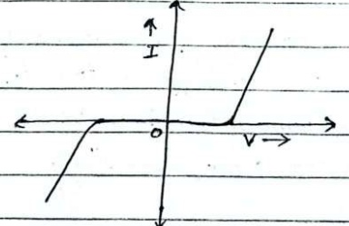
Fig: V-I graph of non-ohmic conductor.
Relationship between current density and electric field strength
If 'I' be the current through a conductor of length 'l' having cross-sectional area 'A' then the current density is given by.
$$ J = \frac{1}{A} \times \frac{V}{R} \quad \left( \because I = \frac{V}{R} \right) $$
Since, \( R = \rho \frac{l}{A} \)
$$ J = \frac{1}{A} \times \frac{V}{\rho \frac{l}{A}} $$
$$ J = \frac{V}{\rho l} $$
$$ J = E \cdot \sigma $$ (\( E = \frac{V}{l}, \sigma = \frac{1}{\rho} \))
Where, 'E' is the electric field strength
And \( \sigma = \frac{1}{\rho} \) is the conductivity of a conductor.
Super conductor
→ The electric resistance of many metals and alloys certainly drops to zero when specimen is cooled to sufficiently low temperature, often at temperature in a liquid helium range (4.2K), this phenomenon is called super conductivity.
→ The property of a material due to which it's resistivity becomes zero at critical temperature, is called superconductivity. And the material exhibiting superconductivity is called superconductor.
Note: An ideal or 'perfect' conductor would have zero resistivity and an ideal insulator would have infinite resistivity.
Perfect conductors
→ A perfect conductor is an electrical conductor with no resistivity. All known perfect conductors are also super conductor.
→ A metal at zero kelvin temperature shows that it has no resistance so in this context the material is a perfect conductor.
→ All metals at zero kelvin temperature behave as perfect conductor.
Perfect Insulators
→ A perfect/ideal insulator is a material having infinite resistivity. For e.g.: glass, rubber are best ideal insulators.
Grouping of resistance
Resistors are to be grouped in circuit to decrease or increase the equivalent resistance of the circuit.
(i) Series combination
The combination in which one end of resistance is connected to the one end of another resistance and so on, so that same current flows through all the resistors then this type of combination is called series combination of resistances.
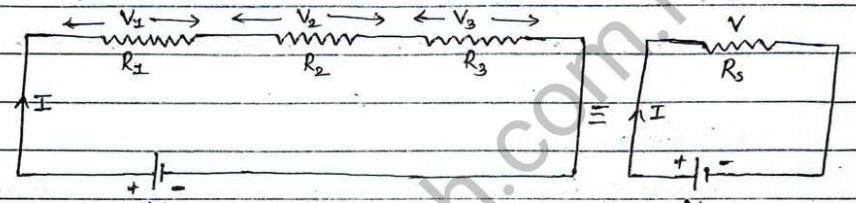
Fig: series combination of resistors. Fig.1 Series equivalent resistance.
Let us consider these three resistors of resistance \( R_{1}, R_{2}, R_{3} \) are connected in series with a battery of potential V. Let 'I' be the current supplied by the battery. Since resistors are in series combination, so same current I' flows through each resistor but potential difference is different depending upon resistance of resistor. Let \( V_{1}, V_{2} \) and \( V_{3} \) be the potential across \( R_{1}, R_{2} \) and \( R_{3} \) respectively. Let equivalent resistance of the circuit is 'R_{s}'. Then,
p.d across \( R_{1} \), \( V_{1}=IR_{1} \)
p.d across \( R_{2} \), \( V_{2}=IR_{2} \)
p.d across \( R_{3} \), \( V_{3}=IR_{3} \)
Now,
Total potential, \( V = V_{1} + V_{2} + V_{3} \)
$$ \text{or,} \quad V=I R_{1}+I R_{2}+I R_{3} $$
$$ \therefore V=I(R_{1}+R_{2}+R_{3}) $$
If \( R_{s} \) is the equivalent resistance of the circuit, then we can write
\( V = I R_{s} \) ①
From ② and ①.
\( I R_{s}=I(R_{1}+R_{2}+R_{3}) \)
\( \therefore R_{s}=R_{1}+R_{2}+R_{3} \) ②
This is the required expression for equivalent resistance in series combination.
Properties of series combination
- Same amount of current flows through all resistors.
- The potential is divided and p.d. is different depending upon resistance of resistor.
- The value of equivalent resistance is equal to the sum of individual resistance.
- The value of equivalent resistance is greater than that of even the greatest resistance.
(ii) Parallel combination
The combination in which one end of all resistors are connected with positive terminal and another end of all resistors are connected with negative terminal of battery so that voltage drop across each resistance remains same is known as parallel combination of resistors.
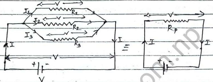
Fig.1 Parallel combination of resistors. Fig.2 Parallel equivalent resistance.
let us consider three resistors of resistance \( R_{1}, R_{2} \) and \( R_{3} \) are connected in parallel combination with a battery of potential V'. Since resistors are in parallel combination, so potential difference across each resistor is same (i.e. V). Let I be the total current supplied by the battery, from point A, the current is divided into \( I_{1} \), \( I_{2} \) and \( I_{3} \) and flows through \( R_{1}, R_{2} \) and \( R_{3} \) respectively. Let \( R_{p} \) be the equivalent resistance of circuit.
Then, Current through \( R_{1} \), \( I_{1} = \frac{V}{R_{1}} \)
Current through \( R_{2} \), \( I_{2}=\frac{V}{R_{2}} \)
Current through \( R_{3} \), \( I_{3}=\frac{V}{R_{3}} \)
Now,
Total current (I) = \( I_{1} + I_{2} + I_{3} \)
$$ I=\frac{V}{R_{1}}+\frac{V}{R_{2}}+\frac{V}{R_{3}} $$
$$ I=V\left(\frac{1}{R_{1}}+\frac{1}{R_{2}}+\frac{1}{R_{3}}\right) $$
The equivalent resistance of the circuit is \( R_{p} \). Then, we can write,
\( \therefore I=\frac{V}{R_{p}} \) → (ii)
from ① and ②.
$$ \frac{V}{R_{p}} = V \left( \frac{1}{R_{1}} + \frac{1}{R_{2}} + \frac{1}{R_{3}} \right) $$
$$ \therefore \quad \frac{1}{R_{p}} = \frac{1}{R_{1}} + \frac{1}{R_{2}} + \frac{1}{R_{3}} $$
∴ This is the required expression for equivalent resistance connected in parallel.
Properties of parallel combination
- The potential difference is same across each resistor.
- The current is divided and the value of current different depending upon resistance of resistor.
- The reciprocal of equivalent resistance is equal to the sum of the reciprocal of individual resistance.
- The value of equivalent resistance is less than that of even the smallest resistance.
Note: If there are two resistors in parallel then to find equivalent resistance, it is better to use the formula.
\( \therefore R_{p}=\frac{R_{1}\times R_{2}}{R_{1}+R_{2}} \) instead of \( \frac{1}{R_{p}}=\frac{1}{R_{1}}+\frac{1}{R_{2}} \)
Potential divider
The arrangement of two resistors in series with a p-d source is called potential divider. It is called so because the two resistors divide potential of the source between them.
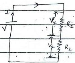
Fig: Potential divider
let \( R_{1} \) and \( R_{2} \) be the two resistance connected in series with a source of p.d V as shown in figure above.
Now, the total resistance of the circuit is
\( R = R_{1} + R_{2} \)
Then, Current through the circuit;
\( I = \frac{V}{R_{1} + R_{2}} \)
Again P.d across \( R_{1} \)
\( V_{1}=IR_{1} \)
\( V_{1}=\left(\frac{V}{R_{1}+R_{2}}\right)R_{1} \) (From ①)
\( \therefore V_{1}=\left(\frac{R_{1}}{R_{1}+R_{2}}\right)V \) → ②
Again, P.d across \( R_{2} \),
\( V_{2}=IR_{2} \)
\( V_{2}=\frac{V}{R_{1}+R_{2}} \times R_{2} \)
\( \therefore V_{2}=\left(\frac{R_{2}}{R_{1}+R_{2}}\right)V \) ③
Dividing eqn (②) by eqn (③), we get.
$$ \frac{V_{1}}{V_{2}} = \frac{\left(\frac{R_{1}}{R_{1} + R_{2}}\right) V}{\left(\frac{R_{2}}{R_{1} + R_{2}}\right) V} $$
$$ \frac{V_{1}}{V_{2}} = \frac{R_{1}}{(R_{1} + R_{2})} \times \frac{(R_{1} + R_{2})}{R_{2}} $$
$$ \therefore \frac{V_{1}}{V_{2}} = \frac{R_{1}}{R_{2}} $$
Current divider
The arrangement of two resistors in parallel with a p.d. source is called current divider. It is called so because two resistors divide current produced by the source between them.
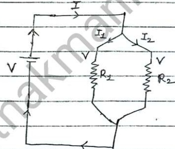
Fig: current divider
let us consider \( R_{1} \) and \( R_{2} \) be two resistance connected parallel with a source of p.d 'V' and 'I' be the total current in the circuit as shown in figure above.
As \( R_{1} \) and \( R_{2} \) are in Parallel. So, total resistance be:
\( \therefore R = \frac{R_{1} R_{2}}{R_{1} + R_{2}} \)
Then, potential difference of circuit is:
\( V = IR \)
\( \therefore V = I \left( \frac{R_{1} R_{2}}{R_{1} + R_{2}} \right) \rightarrow \) ②
$$ I_{1}=\frac{V}{R_{1}} $$
$$ I_{1}=I\left(\frac{R_{2}}{R_{1}+R_{2}}\right) $$
$$ \therefore I_{1} = I \left( \frac{R_{2}}{R_{1} + R_{2}} \right) $$
Similarly, current through \( R_{2} \) is,
$$ I_{2}=\frac{V}{R_{2}} $$
$$ \therefore I_{2} = I \left( \frac{R_{1}}{R_{1}+R_{2}} \right) $$
Dividing eqn (③) by ④,
$$ \therefore \frac{I_{1}}{I_{2}} = \frac{R_{2}}{R_{1}} $$
i.e. \( I\propto\frac{1}{R} \)
Electromotive force (emf)
→ The amount of energy or work done by a source to move a unit positive charge in the closed circuit is called emf of the cell.
i.e. \( emf(E) = \frac{W}{q_{\text{unit charge}}} \)
Differences between emf and p.d.
| Electromotive force (emf) | Potential difference (p.d) |
|---|---|
| The amount of energy supplied by a cell to move a unit positive charge in the closed circuit is called emf of the cell. | The amount of work done by a cell during the movement of a unit positive charge in the circuit is called p.d. of cell. |
| It is denoted by \( E \) | It is denoted by 'V'. |
| It is measured in open circuit. | It is measured in close circuit. |
| It depends on the internal resistance of the cell. i.e. \( E = I(R + r) \) | It is independent on the internal resistance of the cell. i.e. \( V = I R \) |
| It is a cause of p.d. | It is an effect of emf. |
Internal resistance (r)
→ Electric cell is a device which converts chemical energy into electrical energy. An electric cell contains two metallic rod immersed in a liquid contained in a vessel. The liquid is called electrolyte and the rods are called electrodes or plates.
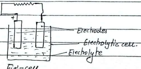
Fig: cell
The electrolyte between two electrodes of cells offers certain amount of resistance when a current flows through it. Thus resistance is called internal resistance of the cell. It is denoted by r' and given by:
We know,
$$ E=I(R+r) $$
$$ Ir = E - IR $$
$$ \therefore r = \frac{E - I R}{I} $$
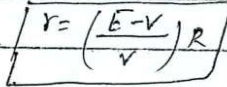
Fig: representation of internal resistance of a cell.
The internal resistance of cell depends upon the following factors:
- nature, temperature and concentration of electrolyte.
- Separation between the electrodes.
- area of immersed portion of electrodes.
Circuit formula: Relation between E, V and r
→ let us consider, a resistance is connected in series with a cell of emf E' and internal (r) as shown in figure above.